Now that we have seen the relational data model and know about relational database schemas we need to learn a good process for creating them. This database design process begins with understanding the information needs in order to determine the records required and the relationships between them. This process of understanding information needs in order to determine what records should be recorded is known as data modeling. The steps to carry out when data modeling in real life look something like this:
- Research the information needs
- Document the information needs in a specification
- Create an Entity Relationship Diagram (ERD) from the spec.
- Convert the ERD into a relational database schema
- Normalize the schema
Some version of this process usually happens whenever an organization needs to create a significant new database. If you were a data modeler carrying out this process for a living, you may begin by interviewing the people in the organization in order to understand their information needs or what kind of information they need to keep track of or are already keeping track of. Once that research has been carried out, it will often be condensed into a set of requirements or a specification (“the spec”). In this class, the specification will be our starting point for data modeling; it will be given to us. Our main task is to create and Entity Relationship Diagram (ERD) from the spec.
To carry out the task of creating and ERD, we create a drawing either by hand or on the computer from the spec. There is more than one standard visual syntax for ERDs that data modelers use. We’ll learn one called Chen Notation which is one of the older forms introduced by Peter Chen in a 1976 paper. Other commonly used ERD notations are Crows foot notation and the Unified Modeling Language (UML). Many organizations will prefer one style or standard over another and require their employees follow it. In this class, our required style is Chen notation; so little to no credit will be given when grading for using a different notation!
We’ve seen entity as a vocabulary word before. It essentially means the same thing as a record. An entity is a collection of related attributes. Said another way an entity is some thing that we can see as separate from other things (other entities). In a class, we may recognize Teacher and Student entities because they are distinct concepts. Similarly, Player and Coach entities may be recognized in sports, Cat and Mouse entities in cartoon violence, and so on. We’ll see defining an entity is somewhat subjective. We try to describe data that we store in terms of distinct groups of information–distinct entities.
An entity set is a set of entities; a set of records of the same type. Relationships may exist between entities. A relationship is a connection between two entities. Drawing an ERD amounts to identifying the entities and relationships in a problem as stated by spec. It is equivalent to identify the records and the relationships between them since entities are synonymous with records.
The best sentences are essentially noun-verb-noun (“The cat ate a Buick.”) The best ERDs can be read like a sentence (“Sailors reserve boats.”). In that sentence the nouns, sailors and boats, are entities while the verb reserve is a connection between the entities. The verb is a relationship. A spec. for the sailing club may be
- Sailors are identified by an id and have a name, age, and rating.
- Boats have a unique id along with a name and a color.
- Sailors reserve boats on a particular date.
Sometimes the spec won’t be a bulleted list. It just depends. The same distillation of an information need could appear as
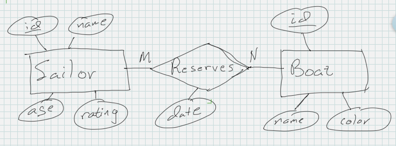
Sailors in the club have an id number, but their name, age, and rating is also recorded. Boats have an id number, too, while the name and color of the boat is tracked. Sailors reserve boats on a particular date. A sailor can reserve the same boat more than once, and a boat can be reserved by many different sailors. Sailors can also reserve many different boats.
These two versions are equivalent, although the second is more verbose. In both of them we see a notion that a sailor is a collection of things–id number, name, age, and rating. Similarly a boat is a collection of id number, name, and color. Each of these things in the collection is a noun, and the name of the collection itself, sailor or boat, is a noun. Out of all these two groups of nouns
- sailor, id, name, age, rating
- boat, id, name, color
Sailor and boat are different from the other nouns in their group because they describe what the collection represent. They’re all related because they’re in a group together, but sailor and boat are bigger because they represent the rest of the nouns. Sailor and boat are the entities and the other are attributes. Id, name, age, and rating are attributes of the sailor entity. Id, name, and color are attributes of the boat entity. Once we’ve identified an entity and its attributes we can draw it in Chen notation. The rules for drawing an entity is that its name goes inside a rectangle while the names of attributes go inside ovals connected to the rectangle. If the entity has a key, an attribute or group of attributes whose value is unique in the entity set, we underline the attribute name(s).
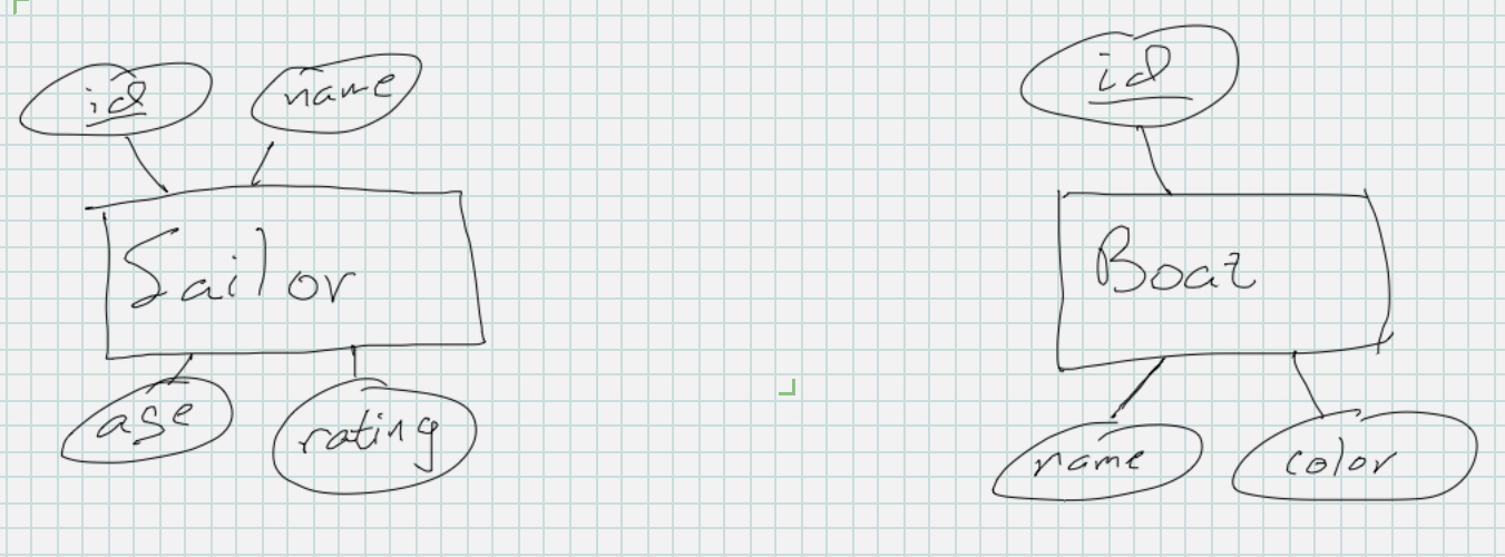
Note that there is no notion of a primary key in ERDs. ERDs are different, separate concepts than a relational database. Relational database tables have primary keys. Entities just have keys. Also note that we draw a single entity in the diagram, but it represents a set of records. The sailor rectangle represents all the sailors that we would need to keep track of. It’s a similar abstraction to a schema diagram where we just include the table name and column headings without filling in the rows in the instance. The ERD is general enough to represent any instance of the actual data.
Now that we have Sailor and Boat entities, we’re not finished. The two entities are connected because a sailor can reserve a boat. We draw this relationship connecting them in a diamond, and we give the relationship a name so that the ERD reads like a sentence either from left to right or top to bottom. In this case we have a nice phrase “sailor reserves boat”. It’s also a common convention to read it in a passive voice when reading from right to left or bottom to top: “boat is reserved by sailor”.
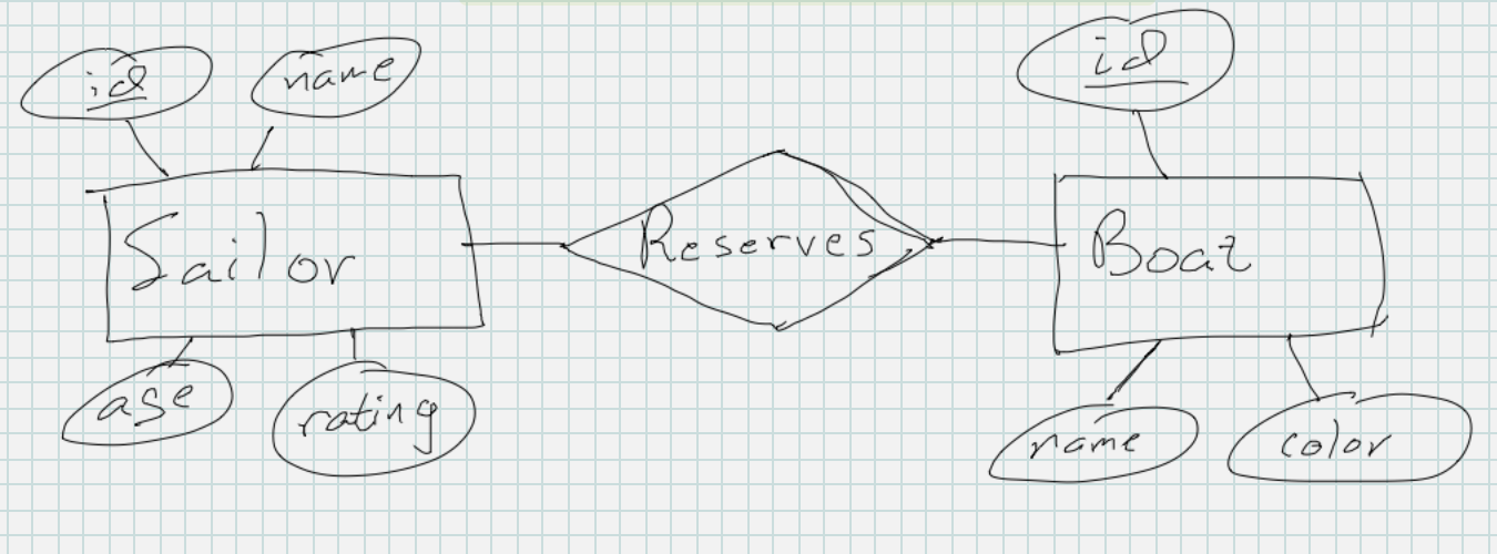
I followed a convention of using singular nouns for the entity names. If I use one singular noun, I need to make sure the rest are singular, too, so that the sentences will read correctly. Another convention is to use plural nouns, and then we would end up with “sailors reserve boats”. Note that all nouns are plural and that the verb/relationship name has changed accordingly so that it reads well. Either choice is good as long as its used consistently; it is not considered a good practice to create ERDs with mixtures that don’t read well.
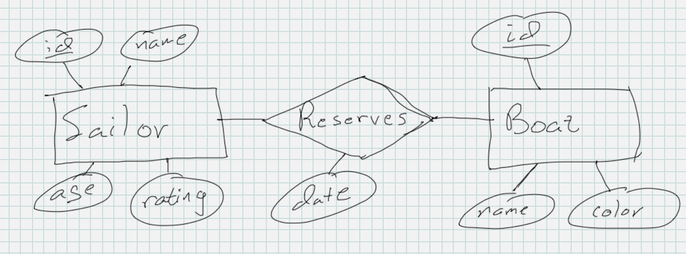
The ERD is not complete, because we haven’t incorporated the fact that we also track the date on which a sailor reserves a boat. It’s a noun, but not a collection of other related nouns, so we expect it to be an attribute. Where does it belong? If we add it to the Sailor entity, it doesn’t make sense since having one date associated with one sailor seems to limit that sailor to just one reservation. Likewise if we add it to Boat, it seems to limit a boat to just one reservation. The solution is that it belongs to the connection between the two, because it’s the sailor and a boat together (the relationship) that happens on a particular date. The visual syntax for indicating this is to once again draw the attribute in an oval but make sure to connect the oval to the diamond signifying the relationship.
Top-level ERDs
As we keep working with ERDs, the specs will get more complicated and our diagrams will get “busier” with many more entities and relationships covering our paper. As these numbers increase, it becomes more difficult to fit them all on the page in a readable, comprehensible way. It’s very common to have to sketch a draft to work out the placement of all the items and then make a final copy. It’s also common to have to erase part of one and re-do it in order to make it all work well.
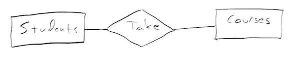
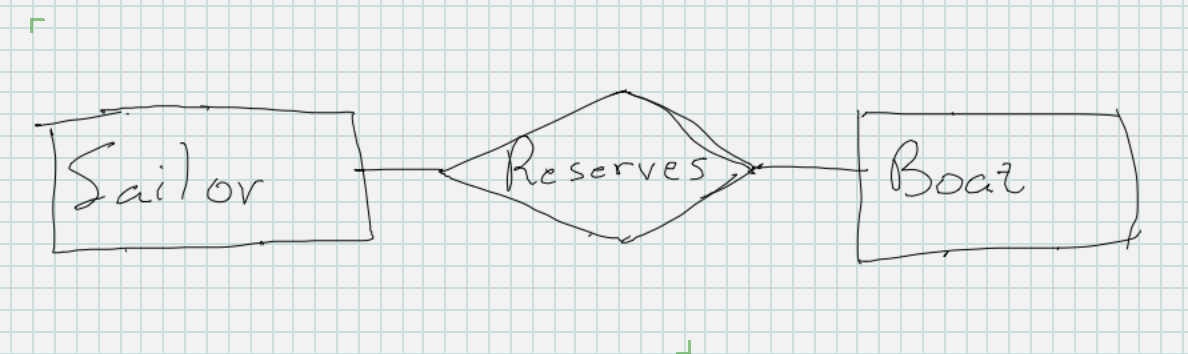
As the number of items increases, fitting all the attributes in becomes a big challenge. There may not be room on the paper, or all the little ovals just may make the diagram unreadable. Attributes are important because they describe the actual data being held, but focusing on them in diagrams sometimes covers up something else equally important: the relationships between records. A top-level ERD is a form of ERD that emphasizes records and relationships but not attributes. They’re easy to draw; just leave out all the attributes and only include entities and relationships. For the sailor reserves boat ERD a top-level entity relationship diagram would look like
Participation Constraints
The visual syntax of Chen notation we’ve seen so far lets us draw ERDs showing the records, their attributes, and the relationships between them. It does not let us fully describe the constraints on those relationships. When we looked at our first logical data models, the flat, hierarchical, and network models, we characterized them based on the kind of relationship between records. The flat model had no relationship between records. The hierarchical model had the parent-child relationship that we called “one-to-many” (a record has at most one parent; a parent can have many children). The network model had the most general relationships that we called “many-to-many”. A record can be related to many other records. Remember that in that context we described the word “many” as simply meaning “more than one”.
In ERDs, the relationships between records can be characterized by their constraints in the same way. They can be many-to-one or many-to-many, which means we can describe hierarchies and networks or records using ERDs. When characterizing the relationships between records, it always helps to have a picture in mind so you can visualize the relationship. Each rectangle in the diagram represents and entity set, a set of records. So we should visualize each Sailor rectangle as standing in for a group of sailors and each Boat rectangle as representing more than one boat.
Relationships are more complicated than entities because they are more abstract. An entity is pretty easy to visualize since it’s just a collection of values where we’ve labeled each value with a name. A relationship is different because it’s primarily a connection between two entities. it may have values associated with it, too, as we’ve seen, but those are optional. The connection is the main part about a relationship.
Once we have these things in mind, we can then visualize the entity sets and the connections between the records in each one. Sailor and Boat have a relationship (Reserves) between them. One sailor reserves one boat at a particular time. That’s just a single relationship between two entities, but the diamond in the ERD represents a relationship set, a group of connections between individual members of the entity set. So the Sailor Reserves Boat ERD represents something like all these records with all these connections between them. Incidentally, a relationship between two different entities like this is called a binary relationship. In class, we’ll also see that there can be unary relationships, ternary relationships, and beyond.
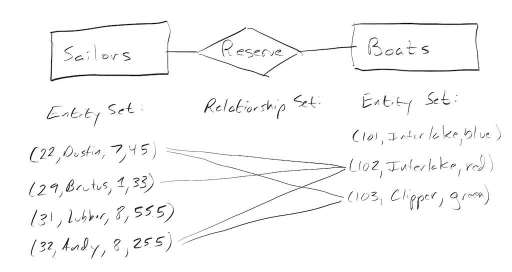
Relationships are described based on how many times an entity participates in the relationship. Dustin participates twice above while Lubber doesn’t participate. On the other side of the relationship, boat 101 doesn’t participate although 102 participates 3 times and 103 twice.
The most exact way of describing how many times is to provide upper and lower bounds for an entity’s participation. If a student was required to take 4 classes every semester and a class could have anywhere from 0 to 20 students, we would describe these participation limits as a lower bound of 4 for Students (a Student would be connected to at least 4 Classes) and a lower bound of 0 for Classes (a Class may not be connected to any students). The upper bounds would be 4 for Students (a student would be connected to at most 4 Classes) and 20 for Classes (a Class could be connected to at most 20 Students).
We’ll see that in Chen notation we are not this precise in how we describe the upper and lower bounds. The upper limit on how many times an entity participates is called cardinality while the lower one is called ordinality. Each is described in turn below.
Cardinality
Now that we have this picture, we can start visualizing what the constraints on the relationships look like. For each entity participating in the relationship, we need to know the maximum number of times it participates (its upper bound). Remember an entity in the entity set “participates” in a relationship every time it’s connected to another entity.
- What’s the maximum number of times can a sailor reserve a boat?
- What’s the maximum number of times a boat be reserved?
Note that the answers to these questions are independent of each other. We can imagine a sailing club where a sailor can reserve more than one boat but never the same one twice. Given this constraint, we can imagine that boats may only be reserved by one sailor (single-use boat) or that boats can be reserved by different sailors (multi-use boat). All of this is to emphasize that for a particular relationship between two entities, there are many different constraints that relationship may have to obey depending on the specific situation or information need being recorded in the data. For the two entities participating in the relationship, we have to ask and answer these questions for each entity; we can’t just focus on one of the entities.
As we saw earlier, all of these questions are about upper limits. The upper bound on how many times an entity can participate in a relationship is called its cardinality, and the most precise answer might be a number like the max. of 20 students in a class above. In Chen notation, though, a less detailed view of cardinality is taken. Instead of any number, there are only two possible answers: “many” or “one”. Many means “more than one” and one means “one”. So Chen notation is not completely precise with regards to cardinality, but at least there’s only two possibilities per entity to worry about. So the full spectrum of possibilities for a relationship between two entities in terms of these upper bounds is
| LEFT Entity (Sailor) | RIGHT ENTITY (Boat) | Cardinality |
|---|---|---|
| Many | Many | Many to many (M to N) |
| Many | One | Many to one (M to 1) |
| One | Many | One to many (1 to M) |
| One | One | One to one (1 to 1) |
We will soon decorate our ERDs with symbols indicating the cardinality of a relationship. When we read the ERDs as sentences, we will use the verbose version of the cardinality column above, adding the words “many” or “one” to the sentence as appropriate. Since there are two entities with each having an upper bound of participation, there are two sentences needed to fully describe the cardinality of the relationship. These two sentences describe a many-to-many relationship.
- A sailor reserves many boats.
- A boat may be reserved by many sailors.
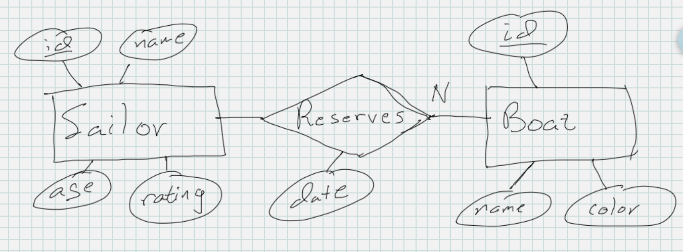
When we decorate the ERD, we use the short form from the cardinality column and decorate our ERD with upper case letters M, N, P, Q, … or 1’s. Note that O (big o) was left out so that it’s not confused with the number 0. We put the letter or 1 for an entity on the opposite side of the relationship’s diamond. This is often confusing to student’s about Chen notation, but it’s the rule. The best way to remember this rule in my experience is that it goes in the same spot it does in the sentence. This ERD shows that “A sailor reserves many boats.”
While this one shows “A boat may be reserved by many sailors”. Remember the ERD in this case is being read from right to left.
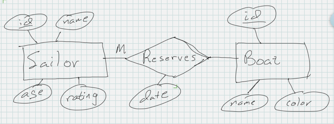
Once we have worked out where each of the symbols goes, we can draw the fully-decorated diagram:
One to many and many to one relationships
The reservations in the sailing club this database keeps track of represent a many-to-many relationship as drawn above in the ERD. Let’s consider a different spec.
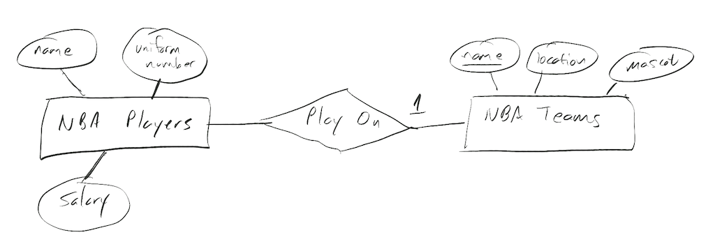
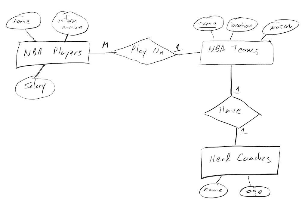
NBA Players have a name, uniform number, and salary. NBA Teams have a unique name, location, and mascot. Teams consist of 12 players while a player must play on only one team.
Hopefully it’s getting easier to spot the two entities and their attributes. Note that the NBA Players entity doesn’t have a key in its description but the Teams entity does. This is not a many-to-many relationship. Its rule is many (12) players play on only one team, and a player can’t play on more then one team. It’s many-to-one or one-to-many depending on which entity we read first (many players one team or one team many players). To indicate this in an ERD, we have to decorate the relationship diamond with a 1 and an M (or another upper-case letter). We put the decorations just as we were reading the sentence, NBA Players (entity/rectangle) play on (diamond/relationsip) at most one (1 decoration) NBA Team (entity/rectangle). This is the ERD:
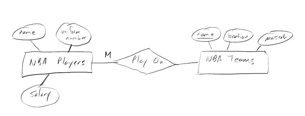
Reading the other direction, we have NBA Teams (entity/rectangle) are played on (diamond/relationsip) by many (M/decoration) NBA players (entity/rectangle), leading to this ERD:
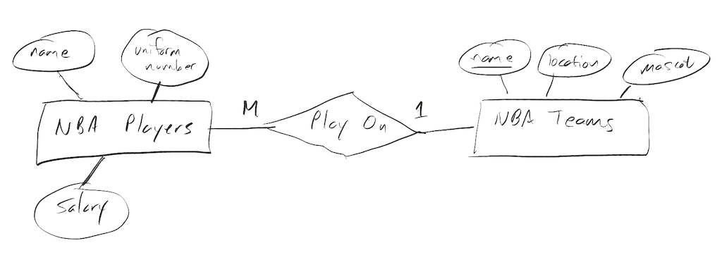
Combining the two yields
One to one relationships
One to one relationships are less complicated than many-to-one because they’re simpler. Each participating entity gets to match up with only one other. We simply decorate each side of the relationship with ones.
NBA Players have a name, uniform number, and salary. NBA Teams have a unique name, location, and mascot. Teams consist of 12 players while a player must play on only one team. Head Coaches have a name and age. Each team has one head coach, and a coach coaches just one team.
We end up with the many-to-one ERD from above and add on the 1-to-1 relationship between Teams and Coaches.
What if the spec. doesn’t indicate cardinality?
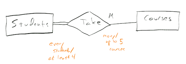
Cardinality may not always be indicated in a spec. Perhaps the details haven’t been worked out yet, or perhaps they just aren’t considered important yet. It’s possible to see a spec describe a relationship like “Students take courses. A student can take up to 5 courses. A course will contain at most 20 students.” In this case we could spot the cardinality for each entity as “many” because the upper limits are all more than 1, being 5 and 20.
With a spec like “Students take courses. A student can take up to 5 courses” we can determine cardinality for Students but not for courses. We must make an assumption. The rule of thumb for making these assumptions is to choose the most general (least constraining) possibility in the absence of information.
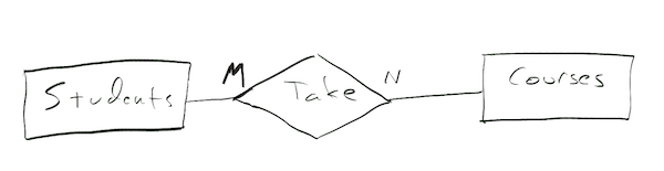
With the least constrained spec “Students take courses” we have to assume cardinality and ordinality for both entities. We choose a cardinality of many and an ordinality of partial participation for both.
Finally, when the information is not known, some practitioners prefer to not decorate the diagram. The single line/partial participation is the default, so an ordinality of 0 is still assumed. But they only decorate the diagram when cardinality is known, and they leave it blank when it is not known.